- 您现在的位置:买卖IC网 > Sheet目录478 > MMA8451QT (Freescale Semiconductor)IC ACCELEROMETER 3AXIS 16QFN
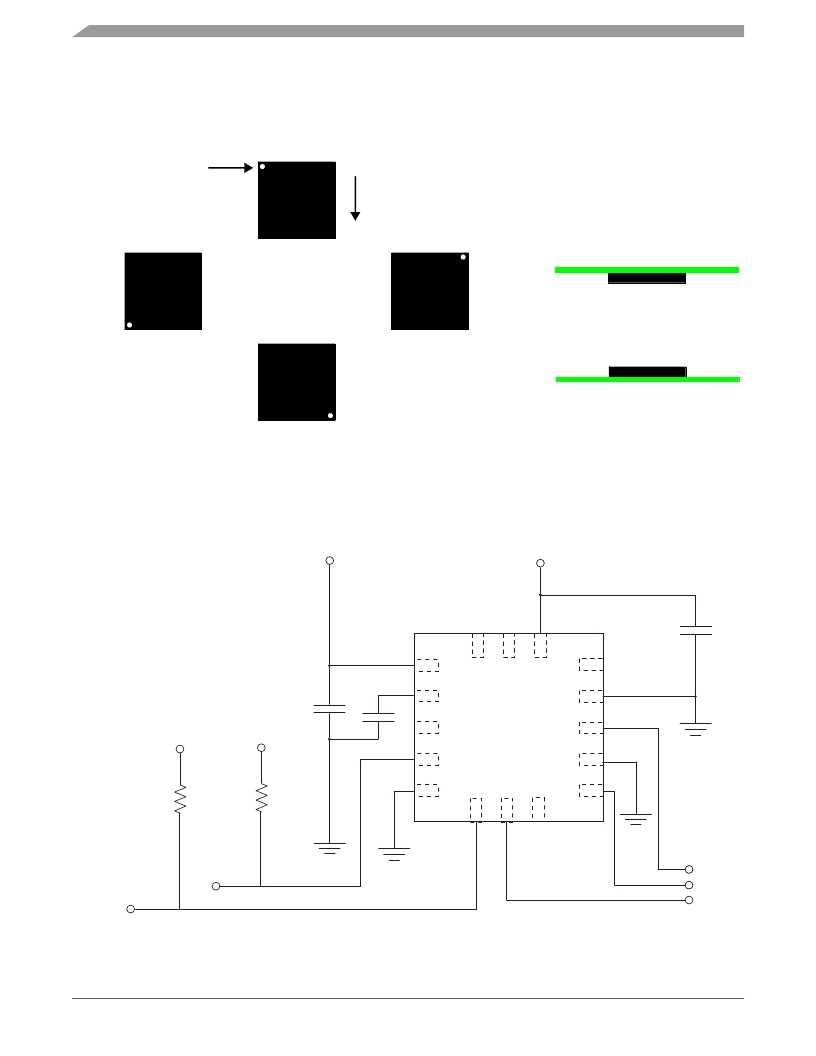
Figure 3 shows the device configuration in the 6 different orientation modes. These orientations are defined as the following:
PU = Portrait Up, LR = Landscape Right, PD = Portrait Down, LL = Landscape Left, BACK and FRONT side views. There are
several registers to configure the orientation detection and are described in detail in the register setting section.
Top View
PU
Pin 1
Earth Gravity
Side View
LL
Xout @ 0g
Yout @ -1g
LR
BACK
Zout @ 0g
Xout @ 0g
Yout @ 0g
Zout @ -1g
PD
Xout @ -1g
Xout @ 1g
Yout @ 0g
Zout @ 0g
Yout @ 0g
Zout @ 0g
FRONT
Xout @ 0g
Yout @ 0g
Zout @ 1g
Xout @ 0g
Yout @ 1g
Zout @ 0g
Figure 3. Landscape/Portrait Orientation
1.6V - 3.6V
Interface Voltage
1.95V - 3.6V
VDD
4.7 μ F
16
15
14
1
2
VDDIO
BYP
NC
GND
13
12
VDDIO
VDDIO
0.1 μ F
0.1 μ F
3
NC
MMA8451Q
INT1
11
4
SCL
GND
10
4.7k Ω
4.7k Ω
5
GND
6
7
8
INT2
9
INT1
SDA
SCL
INT2
SA0
Figure 4. Application Diagram
MMA8451Q
Sensors
4
Freescale Semiconductor, Inc.
发布紧急采购,3分钟左右您将得到回复。
相关PDF资料
MMA8452QR1
IC ACCELER 2G/4G/8G 3AXIS 16QFN
MMA8453QR1
IC ACCELER 2G/4G/8G 3AXIS 16QFN
MMBF0201NLT1
MOSFET N-CH 20V 300MA SOT-23
MMBF170-7
MOSFET N-CH 60V 500MA SOT23-3
MMBF170LT1
MOSFET N-CH 60V 500MA SOT-23
MMBF170
MOSFET N-CH 60V 500MA SOT-23
MMBF2201NT1
MOSFET N-CH 20V 300MA SOT-323
MMBF2202PT1
MOSFET P-CH 20V 300MA SOT-323
相关代理商/技术参数
MMA8452Q
制造商:FREESCALE 制造商全称:Freescale Semiconductor, Inc 功能描述:3-Axis, 12-bit/8-bit Digital Accelerometer
MMA8452QR1
功能描述:加速计 - 板上安装 LOW G 3-AXIS 12BT EX VLT
RoHS:否 制造商:Murata 传感轴:Double 加速:12 g 灵敏度: 封装 / 箱体: 输出类型:Analog 数字输出 - 位数:11 bit 电源电压-最大:5.25 V 电源电压-最小:4.75 V 电源电流:4 mA 最大工作温度:+ 125 C 最小工作温度:- 40 C
MMA8452QT
功能描述:加速计 - 板上安装 LOW G 3-AXIS 12BT EX VLT
RoHS:否 制造商:Murata 传感轴:Double 加速:12 g 灵敏度: 封装 / 箱体: 输出类型:Analog 数字输出 - 位数:11 bit 电源电压-最大:5.25 V 电源电压-最小:4.75 V 电源电流:4 mA 最大工作温度:+ 125 C 最小工作温度:- 40 C
MMA8453Q
制造商:FREESCALE 制造商全称:Freescale Semiconductor, Inc 功能描述:Xtrinsic MMA8453Q 3-Axis, 10-bit/8-bit Digital Accelerometer
MMA8453QR1
功能描述:加速计 - 板上安装 LOW G 3-AXIS DGTL ACCEL
RoHS:否 制造商:Murata 传感轴:Double 加速:12 g 灵敏度: 封装 / 箱体: 输出类型:Analog 数字输出 - 位数:11 bit 电源电压-最大:5.25 V 电源电压-最小:4.75 V 电源电流:4 mA 最大工作温度:+ 125 C 最小工作温度:- 40 C
MMA8453QT
功能描述:加速计 - 板上安装 LOW G 3-AXIS DGTL ACCEL
RoHS:否 制造商:Murata 传感轴:Double 加速:12 g 灵敏度: 封装 / 箱体: 输出类型:Analog 数字输出 - 位数:11 bit 电源电压-最大:5.25 V 电源电压-最小:4.75 V 电源电流:4 mA 最大工作温度:+ 125 C 最小工作温度:- 40 C
MMA8491Q
制造商:FREESCALE 制造商全称:Freescale Semiconductor, Inc 功能描述:Xtrinsic MMA8491Q 3-Axis Multifunction Digital Accelerometer
MMA8491QR1
功能描述:加速计 - 板上安装 3-Axis Low Voltage Discrete Tilt Sensor
RoHS:否 制造商:Murata 传感轴:Double 加速:12 g 灵敏度: 封装 / 箱体: 输出类型:Analog 数字输出 - 位数:11 bit 电源电压-最大:5.25 V 电源电压-最小:4.75 V 电源电流:4 mA 最大工作温度:+ 125 C 最小工作温度:- 40 C
